Conventional threefold scan

vs.

POLYCT threefold scan

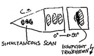
In many applications the efficiency of the Compted Tomography inspection can be significantly enhanced by simultaneous scanning of several parts. By reducing the magnification ratio several objects can be imaged on one detector field allowing to be scanned simultaneously. Whereas for vertically orientated objects the Feldkamp artifact is the main limiting factor, for horizontally arranged objects the penetration capabilities of the X-rays affect the resulting image quality. Thus the reconstruction quality of the simultaneously scanned objects in the horizontal plane can never reach the quality of a single scan.

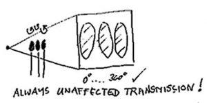
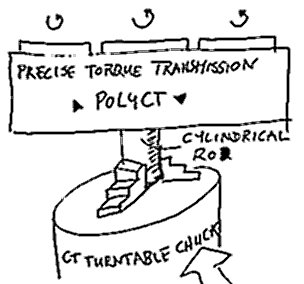
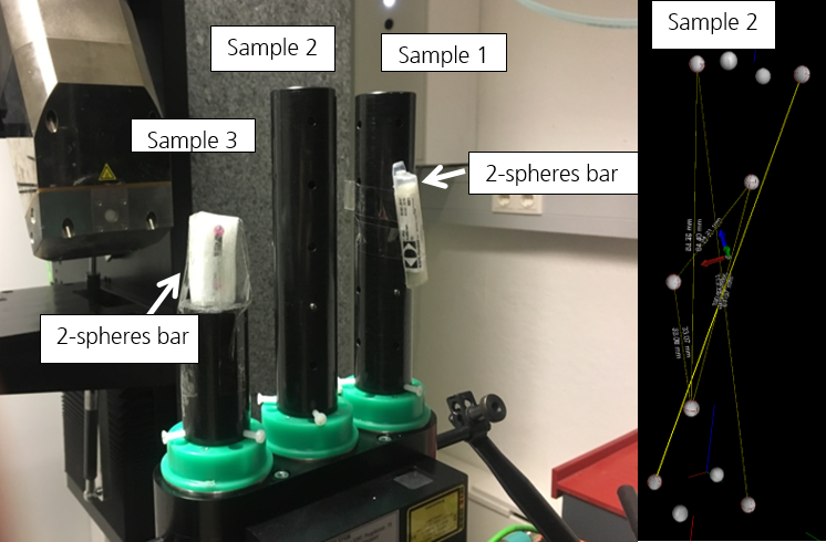
Contrary to the naive simultaneous scan approach where all parts are rotated around one common centre on the sample stage, the POLYCT approach introduces an own rotation axis to each sample allowing to acquire the minimum absorption signal equivalent to a single scan. The simultaneous rotation is transmitted from the existing CT turntable onto three linearly aligned rotation stages positioned on the object plane parallel to the detector plane. Assuming a parallel alignment of the three rotation axes to the detector plane the magnification in each centre of rotation is the same based on the intercept theorem


The new development combines precision mechanics, CT know-how and advanced reconstruction algorithms in an easy-to-use tool for every CT laboratory. The special feature: POLYCT is compatible with all CT systems commonly available on the market and can be put into operation quickly and easily in just a few steps. This enables the user to apply the POLYCT on different CT systems. Due to the passive central rotation axis design, the POLYCT may even remain permanently installed not affecting the functionality and quality of the CT system at all. The set-up effort can thus be minimised even with changing measuring operations. The installation is as simple as inserting a sample. The POLYCT is clamped into the existing chuck of the CT system or fixed to a flat turntable via a centring adapter and locked with a measuring stand against counter rotation. For orthogonal alignment of the POLYCT in the center beam axis, the integrated laser cross (Class A) is projected onto the detector in order to lock it in a recurring, central position. The objects to be tested are fixed in the universally usable specimen holders

Optimum utilisation of the detector area

The POLYCT makes optimal use of the area of the X-ray detector by using individual rotation centres. This has also the effect that far fewer angular steps are required compared to a standard threefold scan. If the detector is divided into thirds, the regular scan can therefore be carried out with up to two thirds fewer images, which has a positive effect on the measurement time. Alternatively, the image quality of the CT scan improves with the same number of angles.

Closed process chain through the use of special software.

The combination of precise mechanics, simple operation and Fraunhofer EZRT reconstruction software makes it easy to use in any test laboratory. The processing of the measurement data is automated by means of the reconstruction software and does not require any intervention in the existing system architecture. The recorded CT data is processed into volume data on a separate customer computer system. Usually it is installed on the existing reconstruction or visualisation client of the existing CT system. The software is compatible to most industrial CT data formats and is contineously extended with every new customer project. Thanks to this closed process chain, the application of the POLYCT requires just minimum user interaction. Based on the customer requirements the functionalities can be further extended.

The reconstructed volume data is stored natively in the Fraunhofer EZRT reconstruction format „*.rek“ and can thus be imported directly into all common visualisation tools. Furthermore the VGStudioMax volume data format „*.vgl“ is available.

Achievable quality and reliability

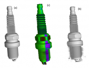
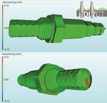
In the example shown above Single spark plugs have been depicted from a standard threefold scan using one turntable (b) and from a POLYCT scan introducing a turntable for each object (a). The central image shows the result of a variance analysis perfromed beteuern the two measurements. The violet regions in the 3D rendering indicate the artifacts related to the elongated penetration path resulting from the threefold arrangement of the spark plugs on one turntable.

The results clearly prove that POLYCT solves the problem of elongated penetration lengths in simultaneous scanning and thus leads to a similar image quality for each sample. 

Nothing is for free so which interferences result from the use of POLYCT?

The remaining interferences can be sorted into two fractions. 1. Physical influences from the slightly different acquisition geometry (described in section „More Theory“) 2. Mechanical influences resulting from the mechanical accuracy and arrangement of the POLYCT device inside the CT system.  First of all the concept of the POLYCT ensures that the centre axis is totally unaffected by any geometrical and mechanical deviations. Due to its direct coupling onto the native rotation axis of the CT system it is just an elevation of the turntable. Thanks to this fact the measurement uncertainty of the two additional rotation axes can be  analysed by a variance analysis between the reconstructions of the two outer turntables and the reconstruction on the centre axis. For this purpose, any object can be scanned alternately on one rotation axis each with constant measurement parameters. Subsequently, all data sets are superimposed and analysed for maximum deviations as shown by the example of a lambda probe. 

For a detailed analysis of the measurement uncertainty a scan of well-known shapes, such as spheres shall be performed on each turntable. In a recent publication the achievable accuracy of the sphere distance measurement between the three axes of the POLYCT have been determined to approx. 10 µm, which is far below the used voxel size of approx. 80 µm.

Mean sphere dist.[mm] ∆ Left [mm] ∆ Centre [mm] ∆ Right [mm]
113.253 -0.013 0.007 0.007
34.646 -0.007 -0.007 0.013
61.676 -0.017 -0.007 0.023
109.963 -0.003 0.007 -0.003
StdDev. 0.006 0.007 0.01

More theory...

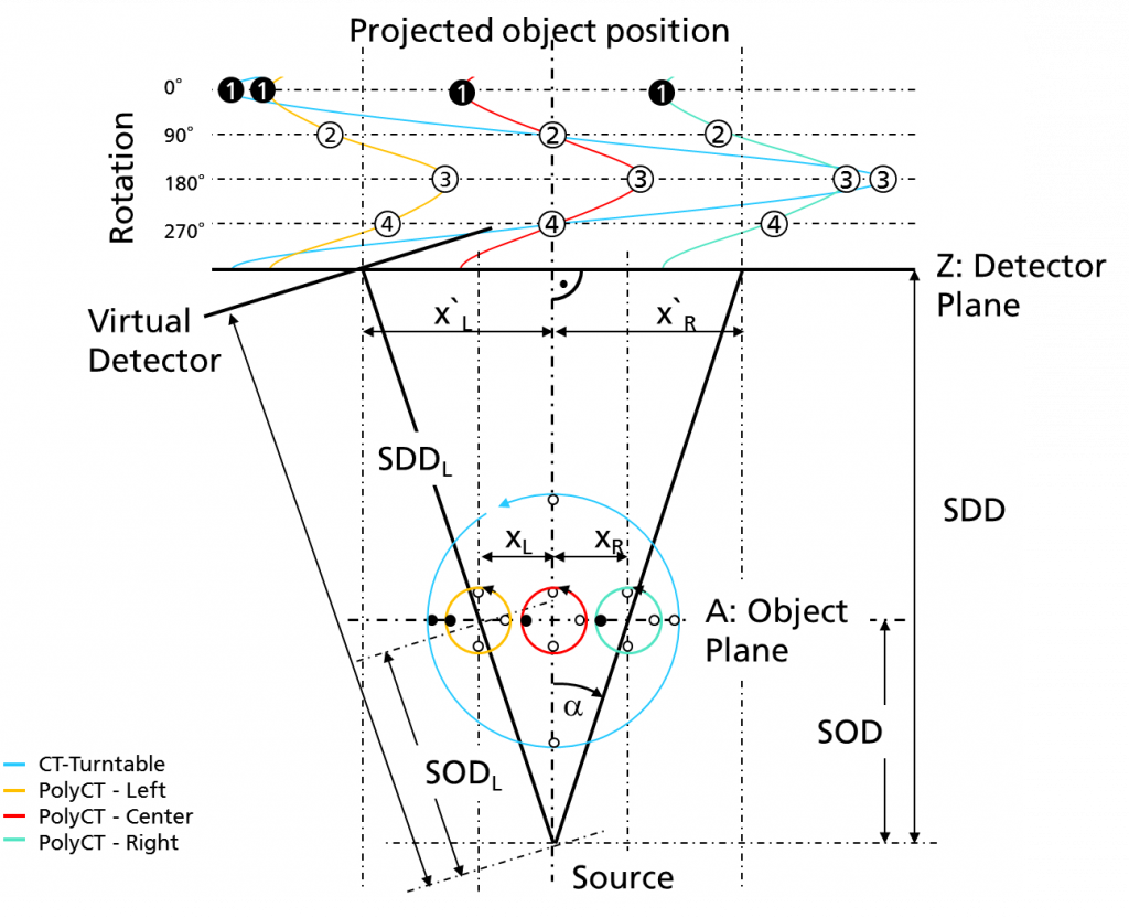
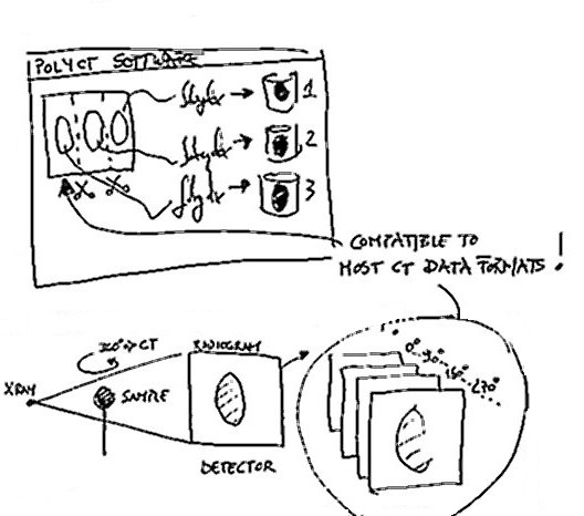
Using POLYCT three datasets are derived from a single scan, whereas the central dataset can be reconstructed natively
due to its symmetry. The two lateral datasets have to be reconstructed considering a virtually misaligned detector shown in Figure left.
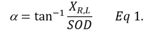
Presuming an orthogonality of the detector plane Z and the central X-ray beam the angular misalignment (a) can be calculated from the distance between the central and the lateral rotation center xL,R and the Source Object Distance (SOD) applied as follows:


Beside the misalignment of the detector plane itself leading to visible distortion artifacts in the reconstructed volume when no correction is applied the geometrical aspects has to be considered. The lateral datasets comprise slightly different SOD and Source Detector Distance (SDD) considering the skew angle

but the voxel size corresponding directly to the magnification factor remains unimpaired as shown by an example calculation for a realistic setup in Table 1.

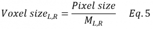
Table 1: Example calculation for a POLYCT setup with xL,R of 25, 50 and 75 mm and a magnification factor of 2 remaining for the central as for the lateral positions


Center dist. xL,R [mm] 0 25 50 75
SDD [mm] 700 701.79 707.2 716.38
SOD [mm] 350 350.89 353.6 358.19
Magnification M 2 2 2 2
a [DEG] 0 4.09 8.18 12.27
SNR [%] 100 99.49 97.97 95.48

Presuming an ideal installation of the POLYCT inside the scanner and a perpendicular beam path to detector setup the only qualitative influence of the POLYCT application is based on a lower Signal to Noise Ratio (SNR) with growing distance from the center plane leading to a nearly neglectable decrease of the SNR shown in Table 1. Thus the application of the POLYCT approach is just limited by physical parameters deriving from X-ray Source and Detector characteristics, alignment features and accuracy of the POLYCT setup itself.

More Paperwork

Nach oben scrollen

POLYREKO

Compatibility
Geomatry Compensation
Fast individual reconstrution